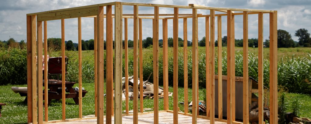
There are regulations in place that require permits for garages, sheds and decks in East Hants. View the information below to learn more about permitting.
Sheds & Garages
Residents constructing sheds and garages on their property are required to obtain a permit.
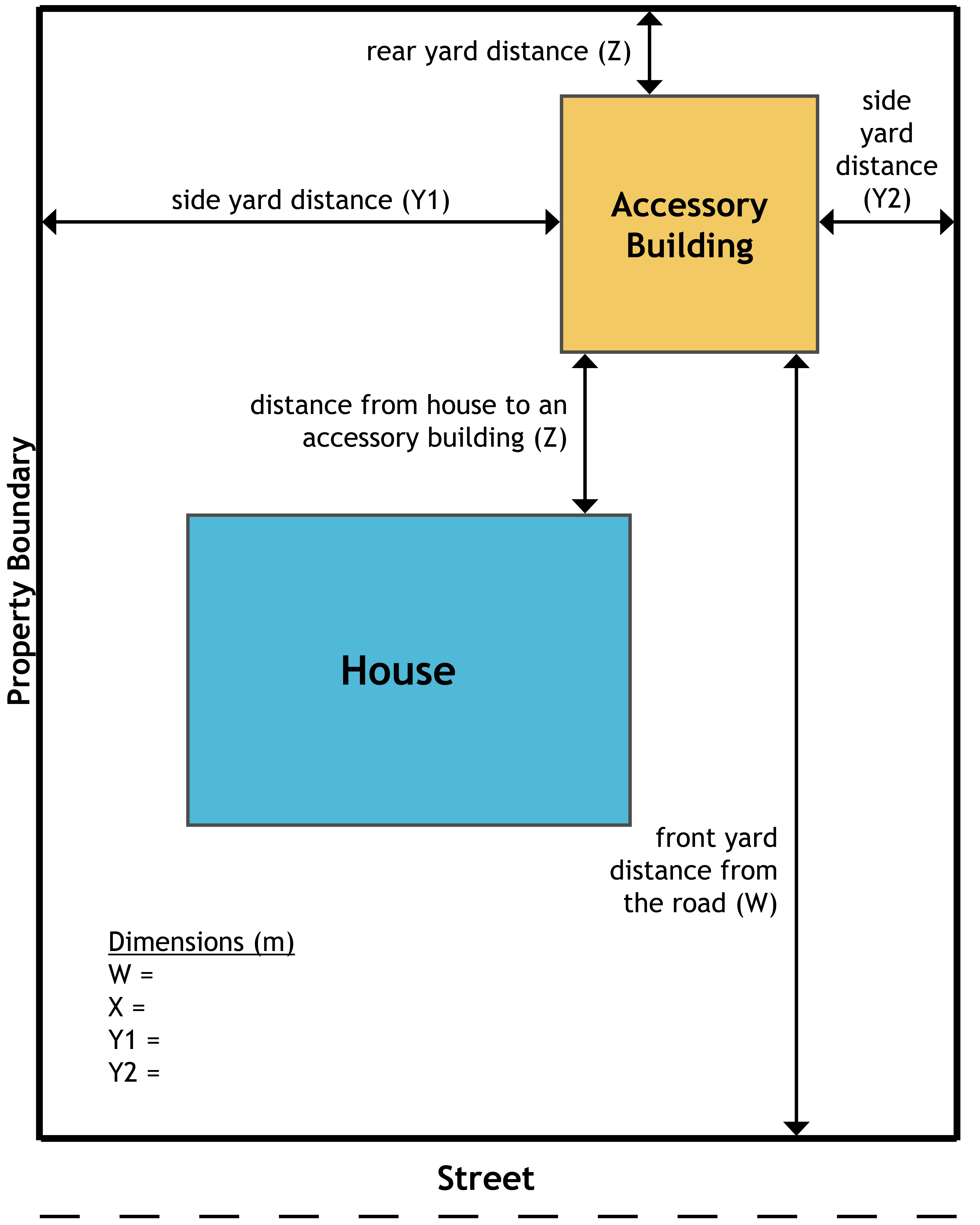
A Plot Plan is required for all permit applications and must show the footprint of the proposed shed or garage and other buildings on the lot. The plot plan shall also include setback dimensions from the side yard property lines, rear and street lines.
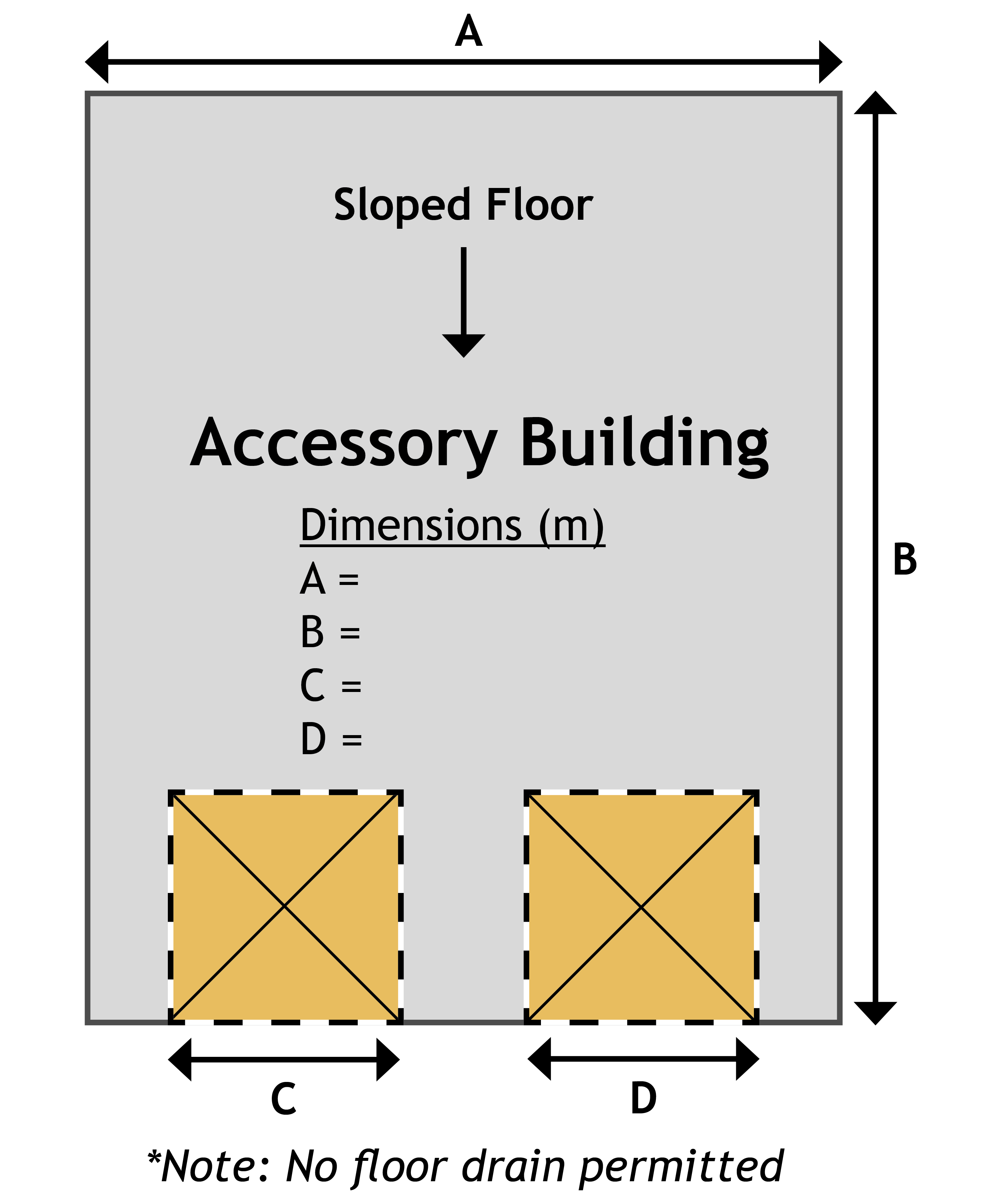
A floor plan must show the interior layout of each floor of the proposed Garage or Shed including:
- The size, spacing and span of framing members
- The location and size of all steps, stairs, etc
- Footing/foundation and or slab design
- Lintel sizes over door and window openings
- Roof construction
You do not require an engineer’s design for a 1.22 metre (four foot) concrete front wall/foundation wall.
A structural thickened edge slab, over 55.7 square metres (600 square feet) requires an engineered design.
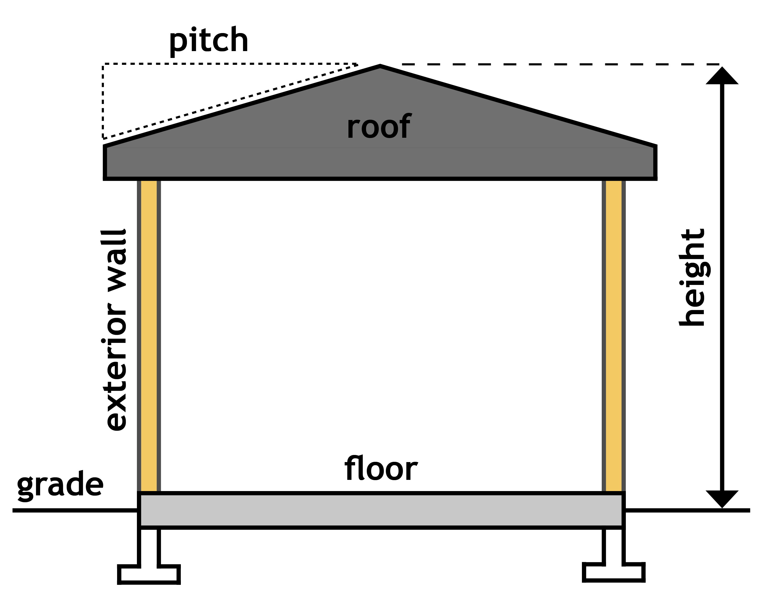
A typical cross section must be taken through an exterior wall from the footing to the roof and show:
- The footing and foundation wall size, list material to be used
- The floor, wall and roof assembly construction; list material to be used
- For lots that are connected to a Municipal wastewater system
- For sheds/garages that are a single storey and over 55 square metres in gross floor area or greater and 2-storey garages of any size
- Read the Lot Grading Bylaw
Information & Regulations
Decks
Residents constructing or rebuilding a deck on their property are required to obtain a permit.
A Plot Plan is required for all permit applications and must show the footprint of the proposed deck, and other buildings on the lot. The plot plan shall also include setback dimensions from the side yard property lines, rear and street lines.
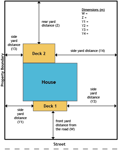
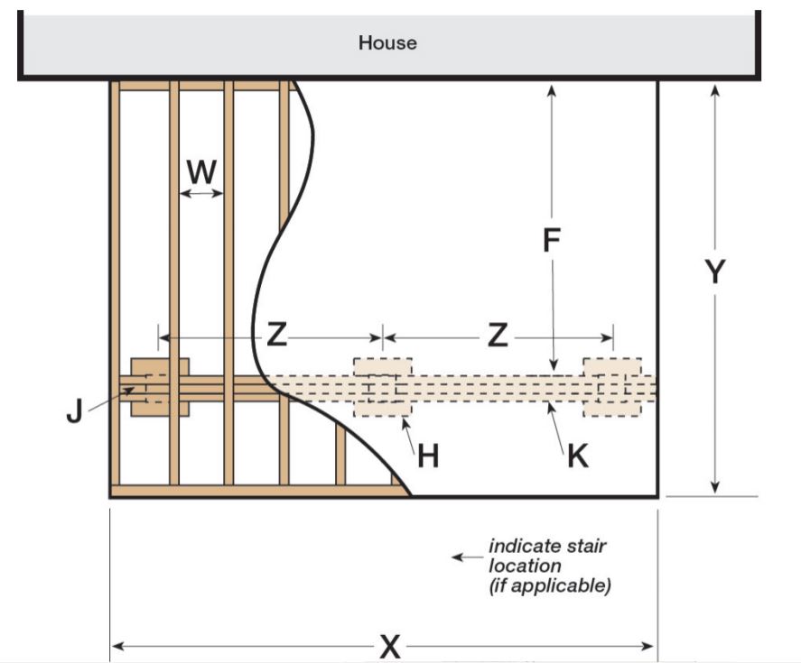
Construction plans show all structural components of the deck including dimensions:
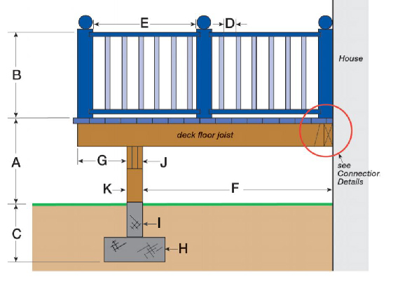
| A | Height of Deck above finished ground level | |
| B | Height of deck guard; if “A” is equal to or less than 6ft – required 36in; if “A” is greater than 6ft – required 42in | |
| C | Footing depth below grade for frost protection – 4ft minimum | |
| D | Openings in the guard = maximum 4in opening | |
| E | Distance between posts | |
| F | Span of floor joist – table below | |
| G | Cantilever (if applicable) | |
| H | Column footing size – width and thickness | |
| I | Concrete column diameter – minimum column size 10in diameter | |
| J | Beam size – table below | |
| K | Wood column supporting wood beam – minimum column size 6in x 6in | |
| W | Joist size and spacing | |
| X | Deck width | |
| Y | Deck Length | |
| Z | Distance between support columns |
Connection Details:
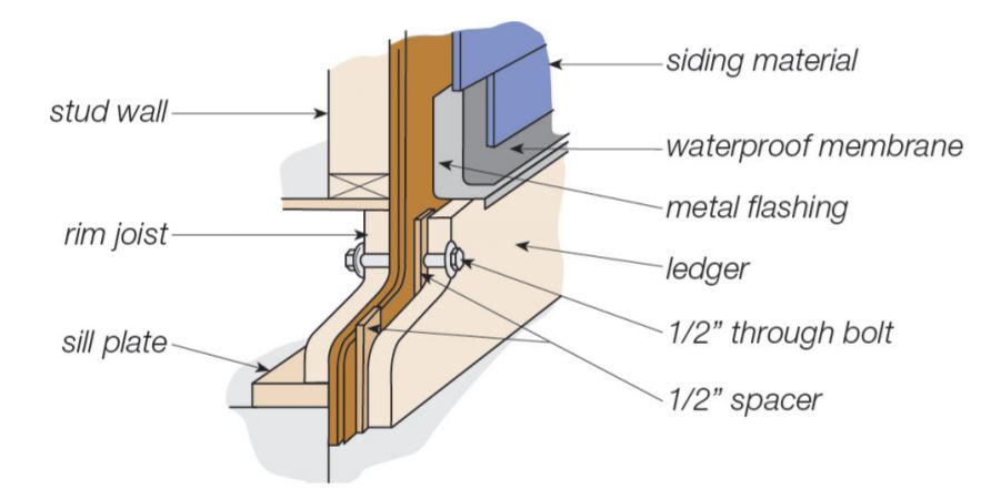
Beams
| Wood Beam Size | Supported Joist Length of Wood Joists | ||||
| 8′-0″ | 10′-0″ | 12′-0″ | 14′-0″ | 16′-0″ | |
| Maximum Span of Wood Beam Between Columns (Z) | |||||
| 3-2″x8″ | 10′-0″ | 9′-4″ | 8′-7″ | 7′-11″ | 7′-5″ |
| 4-2″x8″ | 11′-0″ | 10′-3″ | 9′-8″ | 9′-2″ | 8′-7″ |
| 3-2″x10″ | 12′-10″ | 11′-6″ | 10′-6″ | 9′-8″ | 9′-1″ |
| 4-2″x10″ | 14′-1″ | 13′-1″ | 12′-1″ | 11′-2″ | 10′-6″ |
| 3-2″x12″ | 14′-11″ | 13′-4″ | 12′-2″ | 11′-3″ | 10′-6″ |
| 4-2″x12″ | 17′-2″ | 15′-4″ | 14′-0″ | 13′-0″ | 12′-2″ |
Joist sizes and options
| Lumber Size | Spacing of Joists (K) (on center) | Span (F) | Spacing of joists (K) (on center) | Span (F) |
| 2″x6″ | 16″ | 9′-4″ | 12″ | 10′-4″ |
| 2″x8″ | 16″ | 12′-4″ | 12″ | 13′-6″ |
| 2″x10″ | 16″ | 14′-6″ | 12″ | 15′-8″ |
| 2″x12″ | 16″ | 16′-4″ | 12″ | 17′-9″ |
A deck may be supported with a 10″ sonotube on a 24″x24″ column pad. You may also use a “big foot” and sonotube combination.
Notes: Supported joist length is half the sum of joist spans on both sides of the beam Lumber used for joists, trusses, rafters and beams shall be identified by a grade stamp to indicate its grade as determined by the Standards Grading Rules for Canadian Lumber.
Permitted Overhang: 2″x8″ – 16″; 2″x10″ – 24″
